Sunday, October 14, 2012

Robot Omniwheels

For my senior project, I'm working a robot that balances on a ball to move (ie. a ballbot):

A rendering of my robot's drive assembly -- the motors,  gearboxes, wheels, and the ball it balances on are pictured.

The robot is not statically stable -- there is no orientation for the robot to sit on the ball so that it stays balanced without any movement of the wheels on the ball. It is therefore necessary for the 'bot to have some complicated electronics to stay balanced.

It needs an Inertial Measurement Unit (IMU) with some gyroscopes and accelerometers on it to compute its current angle and speed relative to the ground, and it has to move the wheels according to a control system so that the ball remains under the robot (to stay balanced) or slightly off-center so that the robot moves. I'm going to stop talking about the control system because I haven't really put much more thought into it beyond the preceding two paragraphs (OK, I have, but I don't want to look like an idiot on the internet).

What I have put some thought into, though, is the wheels. Those little cylindrical pieces hugging the ball aren't your run of the mill wheels. The robot has 3 wheels, and if two of them rotate in opposite directions while the third is stationary, the robot will move straight in one direction. However, the stationary wheel shouldn't oppose the motion of the 2 other wheels -- it has to have rollers on it so that it can also move laterally to the normal direction of motion. People have come up with omniwheel designs for this exact purpose:


A typical omniwheel design has rollers on the wheel that allow for lateral movement -- when the wheel moves through the axis of rotation, the small roller it is resting on spins.

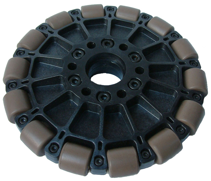
We're not using run of the mill wheels, and we're not even using run of the mill omniwheels. An important characteristic of omniwheels is the contact surface of the wheel with the surface it is rolling on. The above omniwheels have non-continuous contact surfaces: as the wheel rotates, the wheel loses contact with the ground because of the gaps between the rollers. It turns out that it is very hard to construct a wheel with a continuous contact surface, but such a design was patented in Japan in 2001: 
Japanese Patent Publication # 2001-191704. The magic here is that the contact surface is continuous -- when you look at the wheel from the top down view (as seen here), it looks like a perfect circle.
There have been two teams have have built omniwheels according to this design, a Swiss team and a Japanese team:
The Swiss ReZero robot wheel assembly.
The wheel assembly of the robot designed by Kumagai and Ochiai, 2010


Our wheel assembly is very similar to the one created by both groups:

A Solidworks screencap of our wheel. Three of the rollers are transparent to display  more detail about the inside of the wheel.
We've already started manufacturing the wheels; I'll put up more pictures as the construction progresses.

Thursday, September 20, 2012

I try to get out, but they just pull me back in...

The FSAE team wanted to resurrect the 2012 failcar to show off during Cooper Union's annual Fall Festival as a way to lure in unsuspecting freshmen to join the team. One of the major problems in realizing that dream is that the power distribution on the car utterly sucked and probably doesn't work anymore. So, like any respectable engineer, I decided that I could make a new system from scratch that would be better in every way possible. Since I'm not actively participating this year (wait, I guess this is the first time I mentioned that?), I also decided that this project would be a good segue for the next person in charge of the engine and electrical subsystems.

Here is the product of about three days of work:
The schematic. Ain't it pretty? I taught my protégé the fine art of mitering everything so that it looks professional. Ignore the crossed wires though...
Here's the board. The huge traces are because it's rated for automotive things -- 15A pumps, 15A fans, etc. The big rectangular blocks at the sides are kickass solderable lug terminals. The connector at the bottom is a 35-pin right angle ampseal connector.


Since everything had to get done in less than two weeks (and really in the last three days...), we milled the board in-house on 1/2 oz one-sided copper clad using a 1/32" endmill, which is why the trace clearances are so big on the board. I can't decide if this is a stupid and abusive way to use our expensive CNC mill or only just stupid. There are a couple of designed-in flywires on the board since there was literally no way to put more fat traces on the top layer.

Actual board pictures are forthcoming once I get off my butt and take them. The amount of solder I laid on the traces is amusingly stupendous.

Update:
Here are the pictures:
The copper side of the board. Look at those huge blobs of solder! The flywires  are some conduction paths that wouldn't fit on the board. The rectangular bits poking out on the right are the lug slots.

Topside. Looks pretty neat...

Tall, dark, and handsome. Enjoys long walks on the beach and switching motor loads.

Tuesday, September 4, 2012

Equalizer... the stereo one octave edition?

I'm still in GA for a few hours until my flight for NYC leaves, so I spent a few hours reworking my ghetto equalizer. Since more features are always better (amirite guise?), I've changed the design from a mono five band eq to a a stereo eight band eq -- pretty much the threshold at which the thing actually becomes useful instead of a toy.

I changed the design to use the Dangerous Prototypes Sick of Beige PCB profile template because it's more thought out than the mess of arbitrarily placed standoff holes that I had before. The board is also supposedly more "aesthetically pleasing" because the aspect ratio is the Golden Ratio. I personally think that that's a load of garbage, but hey, if anything can make this even more beautiful than I plan on making it, why not? Anyway, the board currently looks like this:


I don't have nearly half the components placed and everything is just in a big blob right now, but... ROUNDED EDGES~!

I'm still sticking to the super awesome OPA1644 opamps, graciously and unknowingly sponsored by TI through their sample program. I'm using the TSSOP packaging this time instead of SOIC. TSSOP is a surface mounted device packaging standard, and SOIC is another. The acronyms are typical irrelevant nonsense, so have this picture instead:

A scaled up picture of SOIC vs TSSOP.
Yeah, this board is basically going to be awesome.

Saturday, September 1, 2012

Dragon*Con

A few weeks ago, my friend Xo invited me to build a robot at the GT Invention Studio for the robot battle competition at Dragon*Con. Since I have more money than sense, I immediately accepted his offer and bought a roundtrip ticket to Georgia.

My stay in Georgia was only going to be a week, so I knew that I had to come up with a simple and robust design since I wouldn't have any time to do any fancy machining or even time to properly debug and battle test my bot. I whipped together a wedge in solidworks:

...not far from the robot's actual geometry
But more seriously, I did design this wedge:


The design consists of two motors attached to gearboxes that are wrapped in a steel cage, and a top steel sheet that has two bends in it. The wedges in the initial design are symmetric. The design is about 3.1 pounds, which is slightly over the 3 lb weight limit of the 'beetle' category I am going to compete in. The design is strong, stiff, and most importantly, very easy to manufacture on a waterjet, a cool little machine that the guys at GT have.

So, anyway, here's the product of about four days of almost nonstop design and fabrication work:

I christen thee "Critical Space Item." May you rip other robots to shreds and achieve great victory... The dings are some battle testing from facing the bot off against a 12 lb robot...

The top shell is the only change from the original design: instead of a symmetric wedge, the wedge on the front is at about a thirty degree angle relative to horizontal and it also has compound bends on the sides to deflect attacks on the wheels. The back looks like this:

GT seems to have an unhealthy fascination with yellowjackets...
The holes all over the shell are to remove unnecessary weight and make it go fast. The slots in the front of the bot are filled with button head screws to make the robot front-heavy and less jittery when moving. It's only somewhat effective; the bot is a skittery crackhead when it comes to turning and runs at 15+ MPH. The bumpers on the wheels are a lame attempt to deflect rear attacks; they tend to bend in practice.

The competition is tomorrow. I hope my bot doesn't get totally destroyed because I'd like to use it as a Roomba back in the office...

Sunday, April 22, 2012

FSAE Weekend 4/21/2012

I went out with the team to the New York Times printing presses in Flushing this weekend to drive the car around in one of their lots. The facility is huge (I think it takes a solid fifteen minutes of walking to get from one end to the other) and their parking lots are correspondingly big.

It was the first time that we've taken the car out since October, and we've gone through very major changes to many subsystems -- a new intake, a new differential, a cable clutch instead of a hydraulic clutch, and some major frame modifications. We have to prove the car all over again and then make sure that each of our drivers is comfortable driving the car and ready for competition.

The event was very useful -- we found a lot of bugs that need to get fixed over the next two weeks. First and foremost, our charging system is broken -- something that I knew about for months but put off way too much. This limited us to a total of 15-20 minutes of driving with a big lead acid battery hooked up in parallel to our tiny two pound LiPoly battery in a total wasted charge setup. The problem seems to be that the regulator/rectifier that converts the 3-phase 60 VAC output of the generator on the engine gets blown out. We run more electrical systems than the stock motorcycle setup and abuse them more -- an electric water pump, a lot of starter motor abuse, and a lot of driver-facing electronics -- that probably over strain the stock rectifier/regulator. I am going to try to hook up another stock R/R and have it hook into the electrical system on a relay controlled by the ECU on engine RPM because I think that the extra power demands of the starter motor at engine start are the biggest strain on the rectifier.

Other bugs that we found are also significant -- we had to kludge an extension mount for our amazing carbon fiber intake because the frame wasn't designed to fit the intake to begin with, but the extension mount seems to leak a little air -- you can hear the hiss of air leaking when the engine is running and it's not coming from the air filter on the intake. The intake is also cantilevered and the mounting flanges are cracking out of the intake runners because of vibration induced crack propagation. We're going to have to hack in another stiff mount at the top end of the intake to fix the problem.

Our brakes aren't in great shape either. We did an acceleration test and tried to lock all four wheels but only two of four locked up. I don't know much about the brake system so I can't say much about how we're going to fix it.

Anyway, not to be totally negative, here's a picture of the car running:


Also, the car didn't leak any water or oil -- that's something that we've had some big problems with in the past few weeks that would have led to a swift disqualification at the competition. We've learned the hard way that you have to do a very thorough job of cleaning sealing surfaces and then applying sealant to them to avoid leaking problems, even in areas that are not highly pressurized.

Friday, April 20, 2012

More and more

I spent most of my day on another project that I am heavily involved with -- the Cooper Union Formula SAE race car. FSAE is an international competition in which collegiate teams build race cars practically from scratch with an eye to smart engineering and economical development. I am the engine tuner, wiring guy, and jack of all trades on the team. The current car has been nearly three years in the works (unfortunately) but we've been testing it since the beginning of this year. It's been a crazy experience and I've learned a tremendous amount from it.

The engine we use is from a Suzuki GSXR 600, a Japanese sports bike that redlines at 14k RPM. The competition rules stipulate a 20 mm intake restriction to choke the engine power, but we still produce about 65 HP brake torque, and there are (bigger and more resourceful) teams that get almost 100 HP out of the thing. I learned a lot from working on the engine -- electronics and sensor wiring in an environment with high EM interference, reliable wiring techniques, and all the fine details of tuning a modern EFI engine. I also appreciate how insanely complicated these engines are -- I have immense respect for the engineers that designed the thing.

We're taking the car out for track testing and driver training this weekend. Hopefully we don't suffer any major breakdowns or setbacks -- if we manage to break in and debug the whole car by the competition date on May 8th we'll be in great shape. I'll try to take some pictures this weekend, but it's hard to capture how excited I am about it.

Wednesday, April 18, 2012

Further Developments

It's been a while since my last post and I have nothing new to report about the Nixie Clock project. I haven't been sitting still though. In February I got my Ultimaker 3d printer kit. It's a fused deposition modeling (FDM) 3D printer design -- basically a glorified hot glue gun.

I had a lot of misgivings about the design before I got the printer because I thought it wasn't mechanically robust or well-designed. The whole thing is made of lasercut birchwood, and I had no idea how it could have good tolerances with such a design. When I got the printer, I had to spend a few weeks on "calibration" -- belt alignment, print bed leveling, print temperature adjustment -- before I got good speed and accuracy. Unfortunately, I don't have any pictures of parts that I've printed yet but there are some good references and examples online. I'll take some pictures soon of some parts that I have printed out that have impressed me -- either for their mechanical stiffness or the good resolution that I was able to achieve.

Anyway, that's not all I've been up to. I'm building an audio amplifier and equalizer and I want to make it really nice. Although the specs aren't anything to call home about -- a 30W amplifier and a 5 band equalizer -- I've tried to treat it like a serious engineering project and put a lot of design and planning work into it. Here's some PCB board images of the amplifier and equalizer, respectively:

amplifier PCB
Amplifier PCB. Look at those fat traces. I had to leave one wire unrouted because there was no were left to squeeze it on -- I'll fly it across the board.

equalizer PCB
Equalizer PCB. I tried to stick to SMD components as much as possible to save space. The opamps are OPA1644 -- really nice quad chips from TI. Nearly all the resistors on the board are 0603 package. It'll be fun soldering them.

I am getting the boards done through Laen's batch order service. He has a really pretty purple soldermask and the boards usually come back with gold ENIG plating instead of cheaper tin HASL plating. I can't wait to get them back, but there is a +2 week turn period from order to delivery. 

Sunday, February 5, 2012

Nixie Clock

I had IN-12 nixie tubes lying around from a batch I bought for a clock that I made a few years ago, and I decided to make a new clock since I had given that old one away. I wanted a sleek and practical clock. The one I am building has:

  • No buttons - time data acquired via a built in GPS unit
  • An anodized aluminum black case
  • A magsafe power connector and cord
  • Six digits - 4 digits for displaying HH:MM and two that cycle between time and temperature
  • Time keeping accuracy of 2 PPM/year courtesy of the DS3231 used for timekeeping
Each of these features took some work, so I'll be going into detail on each in future blog posts.